
Reconstruction#
This section is a step-by-step guide for the process of the reconstruction of the topology of a plant from a point cloud.
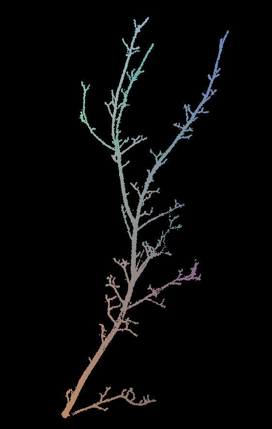
The guide use a 3d point cloud of a branch scanned using a Riegl VZ400 LiDAR as an example.
It is available for download here.
The branch looks as follows after import in plantscan3d:
Point cloud#
Points contraction#
A first step before reconstructing the topology is to contract the
points around the main axis. To do so, click on Points->Contraction,
and choose a contraction algorithm in the list. The Euclidean algorithm
is simple but efficient, so it can be used to contract the points very
quickly. The algorithm giving best results is the algorithm of
Riemannian, which is longer but more precise.
Here is an example result using the algorithm of Riemannian:
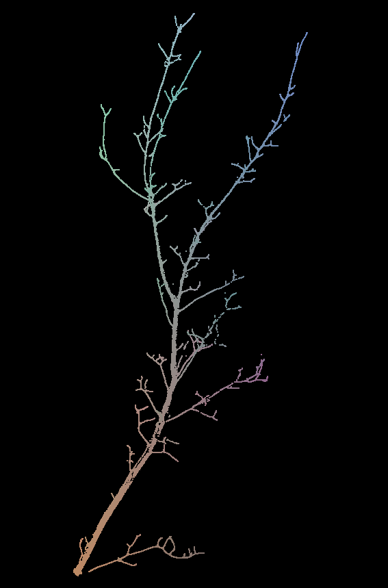
Contracted point cloud#
We can see that the points were contracted along the main axis. This is a key step because it will help the reconstruction algorithm. The objective here is to contract the points to reduce the noise while keeping small structures (a high contraction deforms the structure).
Topology reconstruction#
Add the root#
First, we have to place the first point at the “root” of the structure:
Reconstruction->Add Root->Bottom. It can be the base of a trunk, or
a branch if the point cloud is an isolated branch. You can then move the
point so it is close to the root of the structure. Then, use
right-click->T, or more simply select the point and press T. It
will stick the node to the nearest points.
Skeletization#
The reconstruction of the topology is made using
Reconstruction->Skeletization. Choose an algorithm in the list. It
is recommended to use the algorithm from Xu et al. Then, enter the
number of nodes required from the root until the top of the structure.
For example 50 is a good approximation for a branch.
Now save the resulting MTG File->Save MTG, or press ctrl+S.
Please save frequently in case the application crash.
Display helpers#
The window in the top right corner (Display) proposes 3 helper sliders for visualisation:
Point Sizeto change the size of the LiDAR points
Point size#
Point Filterto filter the LiDAR points that are far from the skeleton. It is used to point out potential reconstruction errors, where some structure is potentially not reconstructed:

Filter points#
Node Size, to control the size of the skeleton nodes:
Node size#
Simple corrections#
It is possible to correct the reconstruction by moving, deleting and adding nodes, or by changing the link between nodes (parent and child).
Moving a node: click on a point and drag it. Change your viewpoint to check if its position is right for all axes. Then, it can be useful to press
Tto “stick” the node to the nearest points, i.e. move it to the barycentre of the local cluster of points.
Add a new node:
N;
Delete a node:
right-click->Remove node;
Add a new node between two nodes:
E;
Correct the parent of a node (wrong connection): select the node, press
P, and select the new parent;
Correct the relationship between two nodes:
A node can either be part of the axis than the previous (it is following in MTG terms), or branching. The relationship
is denoted by the color of the segment between the nodes: white for following, red for branching. It can be changed using
right-click->Set Branching Points or right-click->Set Axial Points (or M).
Note: it is often preferable to re-use the original LiDAR point cloud to correct the skeleton instead of the contracted one. To do so, just re-import the point cloud. It will simply replace the previous one.
Sub-tree corrections#
Sometimes a whole sub-tree need reconstruction. In that case it is possible to delete a sub-tree and to force its reconstruction:
Work with sub-trees#
Smoothing the MTG#
The MTG can be smoothed spatially using
Reconstruction->Skeleton->Smooth
Geometry estimation#
The 3D geometry of the tree can be computed using an estimation of the
diameter of each node. The first step is to re-import the original LiDAR
point cloud to get the right dimensions: ctrl+P.
Please control first that your skeleton reconstruction is good enough compared to the point cloud because it will have a great influence on the estimation of the nodes diameters.
Several algorithms are provided to get the node diameter:
Using the maximum point distance. This can lead to an overestimation of the diameter;
Using the average point distance;
Using the pipe model: only the maximum diameter at the base and at the tip are required:
Then, the diameters can be filtered and smoothed to avoid extreme values and increasing diameters.
The diameter of each node can be controlled by searching through its
properties: right-click->Properties, and scroll until the radius
property.
Finally, a 3D representation can be computed using the diameters and the length of each segment:
Save and export#
The skeleton can be saved as a Multi-scale Tree Graph (MTG). It is
highly recommended to save it as often as possible, especially when
correcting the skeleton. The keyboard short-code is the same as in any
other program: ctrl+S. You can also export the MTG as a list
(File -> Export MTG -> As Node List) and the project as a plantGL
file (File -> Export View -> As PlantGL File) so you can re-import
it using OpenAlea.